| Author |
Message |
LektroiD

Joined: Aug 23, 2008
Posts: 1019
Location: Scottish Borders
Audio files: 2
G2 patch files: 2
|
 Posted: Thu May 12, 2011 8:27 am Post subject: Posted: Thu May 12, 2011 8:27 am Post subject:
|
  |
|
What are the best transistors to substitute for the LM394? I'd rather match my own than spend the rest of my life sourcing such rarities.
Also would they need to be thermally coupled? If I replace the LM394 with individual transistors, one would be the wrong orientation for thermal coupling.
_________________
LektroiD |
|
|
Back to top
|
|
 |
marvkaye
Joined: Mar 14, 2011
Posts: 225
Location: Fla
|
| Posted: Thu May 12, 2011 7:16 pm Post subject:
|
|
|
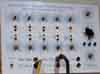
Actually, you can get thermal transfer by twisting both transistors 90 degrees in opposite directions, then leaning them towards each other until their flat faces touch. The picture below is a pair of 2N3904's that I stuck into the same socket that I'd use for an LM394, just to confirm the concept.

They haven't been trimmed yet, nor do they have the thermal body for the tempco. I figured I'd make a teeny aluminum tab that gets epoxied between the flats and sticks up for the tempco(s). In this case, since the tab is rather small, I figured I'd use a pair of 1K SMD's wired in series, glue one to each side of the tab. It should be a pretty nifty package when it's done.
<Marv>
PS... has anyone started on a MOTM/DotCom panel for this yet? If not I may give it a shot... I came up with a nice one for the MFOS CV/Gate Distributor... I'll post it on the MFOS forum one of these days.
Last edited by marvkaye on Thu May 12, 2011 8:54 pm; edited 1 time in total |
|
|
Back to top
|
|
|
marvkaye
Joined: Mar 14, 2011
Posts: 225
Location: Fla
|
| Posted: Thu May 12, 2011 8:33 pm Post subject:
|
|
|
A quick follow-up to my prior post.... here I've trimmed about 3/16" off the leads, got the faces to match up square, and made a little tab out of a piece of aluminum I cut from a pop can with a pair of scissors... it's a bit on the thin side, so I'll probably do the real one with some 15-20 mil stock. The bottom of the flag is cut to a point to match the faces of the transistors. I'm thinking it oughta work like a charm. 

<Marv> |
|
|
Back to top
|
|
|
BananaPlug
Joined: Jul 04, 2007
Posts: 307
Location: Philly
Audio files: 5
|
| Posted: Fri May 13, 2011 5:17 am Post subject:
|
|
|
| Somewhere in my gear I've seen commercially made S shaped clips for that. |
|
|
Back to top
|
|
|
marvkaye
Joined: Mar 14, 2011
Posts: 225
Location: Fla
|
| Posted: Fri May 13, 2011 9:00 am Post subject:
|
|
|
I'm sure somewhere out there someone has come up with a commercial version of this, but 3904's at a nickel apiece just beg for bending, twisting, and lending themselves to a home-brewed solution. This one's mine. 
<Marv> |
|
|
Back to top
|
|
|
fonik

Joined: Jun 07, 2006
Posts: 3950
Location: Germany
Audio files: 23
|
| Posted: Wed May 18, 2011 12:57 pm Post subject:
|
|
|
i uploaded three eurorack FPDs to my site: one for the dual version i built (32HP), one for a single full featured version (16HP), and one for just the core VCO (8HP):
http://www.modular.fonik.de/Page55.html
_________________

cheers,
matthias
____________
Big Boss at fonitronik
Tech Buddy at Random*Source |
|
|
Back to top
|
|
|
jojjelito
Joined: Jun 27, 2007
Posts: 50
Location: Stockholm, Sweden
|
Posted: Wed May 18, 2011 1:43 pm Post subject:
 |
|
|
Hi Mattias!
The PCBs arrived in the mail today. Vielen Dank!
Time to heat up the soldering iron...  |
|
|
Back to top
|
|
|
Captain Biscuits
Joined: Jun 11, 2010
Posts: 116
Location: Northampton, UK
|
| Posted: Wed May 18, 2011 1:47 pm Post subject:
|
|
|
Many thanks Matthias
A pair of very smart red and silver pcbs arrived in the UK today too.
Looking forward to collecting the bits together and getting them made up soon.
Thanks too for the super quick delivery.
All the best
Ian |
|
|
Back to top
|
|
|
brother303

Joined: Nov 02, 2010
Posts: 139
Location: ruhr-area/germany
|
| Posted: Wed May 18, 2011 2:20 pm Post subject:
|
|
|
Hi Fonik,
just took a quick look on your building docs and some questions came up :
- what`s the function of the connect 1 + 2 trimpots?
- how to adjust the hf-trim?
- how to wire j4 (hard sync)?
Thanks!
_________________
Best regards
Greg |
|
|
Back to top
|
|
|
fonik
Joined: Jun 07, 2006
Posts: 3950
Location: Germany
Audio files: 23
|
| Posted: Thu May 19, 2011 1:28 am Post subject:
|
|
|
_________________
cheers,
matthias
____________
Big Boss at fonitronik
Tech Buddy at Random*Source |
|
|
Back to top
|
|
|
tehskull
Joined: May 07, 2011
Posts: 23
Location: Kentucky
Audio files: 1
|
| Posted: Thu May 19, 2011 8:01 am Post subject:
|
|
|
Hello. Would it be possible to put me down for 2 PCB sets?
Thanks! |
|
|
Back to top
|
|
|
fonik
Joined: Jun 07, 2006
Posts: 3950
Location: Germany
Audio files: 23
|
| Posted: Thu May 19, 2011 8:14 am Post subject:
|
|
|
check PM (your email is not active)
_________________
cheers,
matthias
____________
Big Boss at fonitronik
Tech Buddy at Random*Source |
|
|
Back to top
|
|
|
brother303
Joined: Nov 02, 2010
Posts: 139
Location: ruhr-area/germany
|
| Posted: Thu May 19, 2011 8:29 am Post subject:
|
|
|
Hi Fonik,
thanks for reply,useful as always...
Regarding j4/hardsync : I didn`t realize that a JACK is wired up to j4,always thought of a SWITCH... 
_________________
Best regards
Greg |
|
|
Back to top
|
|
|
emdot_ambient
Joined: Nov 22, 2009
Posts: 667
Location: Frederick, MD
|
|
|
Back to top
|
|
|
brother303
Joined: Nov 02, 2010
Posts: 139
Location: ruhr-area/germany
|
| Posted: Thu May 19, 2011 8:59 am Post subject:
|
|
|
Hi,
| emdot_ambient wrote: |
"A" is for "apple"
"J" is for "jack"
... |

_________________
Best regards
Greg |
|
|
Back to top
|
|
|
rosch

Joined: Oct 03, 2009
Posts: 164
Location: germany
|
| Posted: Fri May 20, 2011 4:28 am Post subject:
|
|
|
they arrived today!
thank you very much for this project! |
|
|
Back to top
|
|
|
brother303
Joined: Nov 02, 2010
Posts: 139
Location: ruhr-area/germany
|
| Posted: Fri May 20, 2011 7:55 am Post subject:
|
|
|
Yup,
my pcbs also arrived today. 
Cheers!
_________________
Best regards
Greg |
|
|
Back to top
|
|
|
tokyomatik

Joined: Jan 20, 2011
Posts: 171
Location: berlin
Audio files: 6
|
| Posted: Sat May 21, 2011 4:48 am Post subject:
|
|
|
hi mattias
i received the pcbs and i have to say you did a great job.
all the connections for pots and jacks are made just to keep the soldering work fast, easy and clear.
thanx a lot |
|
|
Back to top
|
|
|
adambee7
Joined: Apr 04, 2009
Posts: 420
Location: united kingdom
|
| Posted: Sat May 21, 2011 5:28 pm Post subject:
|
|
|
| boards arrived. cheers chap. |
|
|
Back to top
|
|
|
droffset

Joined: Feb 02, 2009
Posts: 515
Location: London area
Audio files: 2
|
|
|
Back to top
|
|
|
kupfer_m
Joined: Oct 14, 2010
Posts: 48
Location: Belgium
|
| Posted: Mon May 23, 2011 1:27 am Post subject:
|
|
|
| I received my boards too! |
|
|
Back to top
|
|
|
arsonus
Joined: Apr 17, 2011
Posts: 14
Location: Slovakia
|
| Posted: Mon May 23, 2011 2:24 am Post subject:
|
|
|
Boards arrived today!
Thanks a lot!
|
|
|
Back to top
|
|
|
LektroiD
Joined: Aug 23, 2008
Posts: 1019
Location: Scottish Borders
Audio files: 2
G2 patch files: 2
|
| Posted: Tue May 24, 2011 4:30 am Post subject:
|
|
|
The 3904 matched pair looks great, I'll be using these in conjunction with SMD tempcos (2K/3000ppm), hopefully that'll be close enough to the mark.
Also, how essential is R54? The only 1.5MΩ I have is 5%.
_________________
LektroiD |
|
|
Back to top
|
|
|
fonik
Joined: Jun 07, 2006
Posts: 3950
Location: Germany
Audio files: 23
|
| Posted: Tue May 24, 2011 4:40 am Post subject:
|
|
|
| LektroiD wrote: | | Also, how essential is R54? The only 1.5MΩ I have is 5%. |
not that essential. actually everyhting should work fine with 5% resistors, even R27...
nevertheless, for the resistors in the sine waveshaper (R10-11, R16-1 i would use 1% resistors. i would use 1% resistors.
_________________
cheers,
matthias
____________
Big Boss at fonitronik
Tech Buddy at Random*Source |
|
|
Back to top
|
|
|
tokyomatik
Joined: Jan 20, 2011
Posts: 171
Location: berlin
Audio files: 6
|
| Posted: Tue May 24, 2011 9:11 am Post subject:
|
|
|
i'm searching for some trimmers but i have only 1/2w for the 100ohms
does it make a lot difference or it should be 1/4w? |
|
|
Back to top
|
|
|
|

 Forum index » DIY Hardware and Software » fonik's place

