| Author |
Message |
brother303

Joined: Nov 02, 2010
Posts: 139
Location: ruhr-area/germany
|
 Posted: Sun Mar 27, 2011 7:37 am Post subject: Posted: Sun Mar 27, 2011 7:37 am Post subject:
|
  |
|
Hi,
| Pantheon wrote: | Ah yes its a 1M resistor, but it realy isnt that important, 47k or something might be more resonable  It was just to tie that end of the cap to ground. It was just to tie that end of the cap to ground.
I hope it works for you, let us know your results! |
 Thanks,I´ll try a 47K. Thanks,I´ll try a 47K.
| Pantheon wrote: | | I finished checking my board layout, and after a couple of tweaks everything looks good and checks out ok ...Once i'm happy that its working correctly, i'll post up the final layout, schematic, parts placement, etc. |
Sounds goooood!
| Pantheon wrote: | Does anyone have any good tips on how to apply text to a face plate?
I have tought about toner transfering it on, then sealing it with some spray. My dad suggested silk screening, but I dont have any idea how its actualy done. |
How about water decals? Something like this...
http://www.mcgpaper.com/decals.html
...and here is another interesting one...
http://www.strings.ph.qmw.ac.uk/~thomas/synthdiy/frontpanel.htm
Helpful?
Cheers
Greg |
|
|
Back to top
|
|
 |
brother303
Joined: Nov 02, 2010
Posts: 139
Location: ruhr-area/germany
|
| Posted: Sun Mar 27, 2011 2:32 pm Post subject:
|
|
|
Hi Pantheon,
have built the vca.
The cv side seems to work out correctly,but I have problems in the audio-path.
I tried attenuating the input signal (Wiard Anti-osc/Hertz Donut/Arp-VCO) but it always sounds very distorted and the high freqs are cut off massively. 
Have to go thru the circuit once again...
What is the correct mounting-direction of c2 and c4?
- C2 : "+" > right
- C4 : "+" > left
Can you confirm this?
Ah,and please,could you run a saw wave thru your Spice simulation to see if the highs are cut off?
Many thanks and best regards (as always...  ) )
Greg |
|
|
Back to top
|
|
|
Pantheon

Joined: Feb 17, 2011
Posts: 36
Location: Edinburgh
|
| Posted: Sun Mar 27, 2011 3:02 pm Post subject:
|
|
|
Ah sorry to hear its not working correctly,
I'll get back to you with the details in a couple of minutes.
_________________
the8bitpimp.wordpress.com |
|
|
Back to top
|
|
|
remork
Joined: Aug 02, 2009
Posts: 25
Location: bhellgium
|
| Posted: Sun Mar 27, 2011 3:18 pm Post subject:
|
|
|
wow, first time reading through this topic. great work so far!
got so much catching up to do..
nothing to contribute to the tech discussion, but i can tell you that screenprinting an already drilled plate is not gonna work as you'd probably tear up the screen. not too many printers would be happy about that.
undrilled plates would work (if the edges are rounded/deburred!), but preparing a screen for a single print is a pain in the *ss.
larger numbers are definitely more interesting when screenprinting, since preparations can take a couple of hours before you can actually start printing.
..i'd go with the decals if i were you |
|
|
Back to top
|
|
|
Pantheon
Joined: Feb 17, 2011
Posts: 36
Location: Edinburgh
|
| Posted: Sun Mar 27, 2011 3:43 pm Post subject:
|
|
|
I had used the vca provided by eric as a basis, so you can look at that for the most part: http://urekarm.tripod.com/synth/jx_vca.pdf.
Yes your cap orientation seems correct.
I have tried a few things in the simulation and yes I also have found that it was cutting off the high-frequencies. Here is what I found:
If you look at Erics VCA, in the feedback loop of the first opamp, there is a [4n7 and 100k] from the output to the negative input. I think this is there to compensate for the High-frequency loss. I stupidly removed that from my schematic for some reason, but when I added it to my simulation the highs arnt as rolled off. You could try adding them in and see if that corrects the problem. I cant think right now why you would be getting such distortion
You can try pulling lower Transistor out entirely, the one with its collector at ground. That would be a little more true to the original MS20 vca.
Let me know if that EQ fix works and then we can see how to tackle the distortion
Thanks for you input Remork, yes it sounds like I should give screen printing a miss for this pannel. I got a little excited and couldnt help myself but to start working on the pannel. I will definately look into transfers for this.
Im looking forward to getting this board etched tommorow.
Im going to stick two VCO's onto one PCB I think, and the ring mod with the octave/finetune curcuits for each VCO on another, making just two PCBs for two vcos, much easier to mount.
_________________
the8bitpimp.wordpress.com |
|
|
Back to top
|
|
|
ericcoleridge

Joined: Jan 16, 2007
Posts: 889
Location: NYC
|
| Posted: Mon Mar 28, 2011 1:07 pm Post subject:
|
|
|
| brother303 wrote: |
have built the vca.
The cv side seems to work out correctly,but I have problems in the audio-path.
|
Did you try my layout? |
|
|
Back to top
|
|
|
Sebo

Joined: Apr 27, 2007
Posts: 564
Location: Argentina
|
|
|
Back to top
|
|
|
Pantheon
Joined: Feb 17, 2011
Posts: 36
Location: Edinburgh
|
|
|
Back to top
|
|
|
ericcoleridge
Joined: Jan 16, 2007
Posts: 889
Location: NYC
|
| Posted: Mon Mar 28, 2011 8:46 pm Post subject:
|
|
|
| As I remember it, it was difficult to discern the behavior of the VCA on the MS20, cause it's always hardwired to ENV Gen 2, and can't be disconnected. There's an "initial cv" input without an attentuator. As I remember, it's kind of a crappy VCA. |
|
|
Back to top
|
|
|
brother303
Joined: Nov 02, 2010
Posts: 139
Location: ruhr-area/germany
|
| Posted: Tue Mar 29, 2011 2:48 am Post subject:
|
|
|
Hi Eric,
| ericcoleridge wrote: | | brother303 wrote: |
have built the vca.
The cv side seems to work out correctly,but I have problems in the audio-path.
|
Did you try my layout? |
I tried the first layout posted by Pantheon and used yours as a reference.
| Pantheon wrote: | | Let me know if that EQ fix works and then we can see how to tackle the distortion Smile |
I´m still into this,will post my results soon!
I´ll have a look at the Takeda-vca as well...hm,why did he take a tl084 with only a quarter of it used? A tl072 should do it,or am I wrong here?
Cheers
Greg |
|
|
Back to top
|
|
|
Pantheon
Joined: Feb 17, 2011
Posts: 36
Location: Edinburgh
|
| Posted: Tue Mar 29, 2011 6:41 am Post subject:
|
|
|
| brother303 wrote: |
I´ll have a look at the Takeda-vca as well...hm,why did he take a tl084 with only a quarter of it used? A tl072 should do it,or am I wrong here?
|
A tl072 will do absolutely fine. I think he uses a TL084 because he built the VCA and the VCF together.
[edit]
Im etching up the dual vco board right now
- toner has transfered fairly well, just a few touch ups needed.
- its sitting in feric chloride as i type this
[/edit]
[edit 2]
- it is now etched and trimmed
- i might start the drilling now, and i need to order some more parts from Rapid.
[/edit 2]
_________________
the8bitpimp.wordpress.com |
|
|
Back to top
|
|
|
brother303
Joined: Nov 02, 2010
Posts: 139
Location: ruhr-area/germany
|
| Posted: Wed Mar 30, 2011 4:46 am Post subject:
|
|
|
Hi Pantheon,
vca is working and yes,it`s not a "high-end" sounding one. But that´s MS20,isn`t it?
The distortion-bug was gone after resoldering a wire,my fault... 
Any idea how to improve the high freqs at 10k and above? I added the 4n7 and a 100k resistor as you suggested and the behavior was much better. Perhaps increasing the value of the 4n7 gives less high cut?
| Pantheon wrote: | | A tl072 will do absolutely fine. I think he uses a TL084 because he built the VCA and the VCF together. |
Ah,I see. Reading schematics is helpful sometimes...
Cheers
Greg |
|
|
Back to top
|
|
|
Pantheon
Joined: Feb 17, 2011
Posts: 36
Location: Edinburgh
|
| Posted: Wed Mar 30, 2011 3:00 pm Post subject:
|
|
|
Great news 303, do you have any idea if it has "the ms20 sound"?
I cant think right now of a good way to improve the eq, i'll have a closer look at the ms20 vca from the service manual and see if i notice anything.
Did you try to remove the lower transistor, to see what effect that would have on the sound?
_________________
the8bitpimp.wordpress.com |
|
|
Back to top
|
|
|
ericcoleridge
Joined: Jan 16, 2007
Posts: 889
Location: NYC
|
| Posted: Wed Mar 30, 2011 3:18 pm Post subject:
|
|
|
| brother303 wrote: |
Any idea how to improve the high freqs at 10k and above? I added the 4n7 and a 100k resistor as you suggested and the behavior was much better. Perhaps increasing the value of the 4n7 gives less high cut?
|
Isn't it possible that what you're experiencing as freq loss might be a design characteristic put in place to compensate for other parts of the circuit (VCOs, VCFs, etc)? I'd be a little disappointed if I built this VCA and didn't find some sort sound coloring. Just a thought. |
|
|
Back to top
|
|
|
Sebo
Joined: Apr 27, 2007
Posts: 564
Location: Argentina
|
| Posted: Wed Mar 30, 2011 7:14 pm Post subject:
|
|
|
Well, I have a Korg MS-10, if you want to run some tests on it, let me know what you want.
It has an audio in, I can do some spectrum tests...
_________________
Sebo
---------------------------------------
My Music:
https://www.facebook.com/cosaquitos/ |
|
|
Back to top
|
|
|
brother303
Joined: Nov 02, 2010
Posts: 139
Location: ruhr-area/germany
|
| Posted: Mon Apr 04, 2011 3:01 pm Post subject:
|
|
|
Hi all,
found some time today to play around with the vca (wiring up a Klee is an absolutely time-killer...).
| Pantheon wrote: | | Great news 303, do you have any idea if it has "the ms20 sound"? |
| ericcoleridge wrote: | | Isn't it possible that what you're experiencing as freq loss might be a design characteristic put in place to compensate for other parts of the circuit (VCOs, VCFs, etc)? I'd be a little disappointed if I built this VCA and didn't find some sort sound coloring. |
It´s no high-end vca, it´s definatly coloring,but it does its job as a sound-shaping element in the signal chain. One can like it or not.
I think,it`s the combination of vcos,vcf + vca,which makes the "ms20-sound" as we know it.
Will be interesting to hear this little sucker combined with the R.Schmitz-vcf and Pantheons vcos. And even more interesting to hear the vco/vcf-combo thru a "modern" vca,e.g. Doepfers a-132-3,which I like very much.
| Pantheon wrote: | | Did you try to remove the lower transistor, to see what effect that would have on the sound? |
Yes. It´s getting louder and the high freqs seem to be more present. Think I like it better this way.
| Sebo wrote: | Well, I have a Korg MS-10, if you want to run some tests on it, let me know what you want.
It has an audio in, I can do some spectrum tests... |
Hi Sebo,would be cool if you could record two short audio-snippets.
1. A vco of your choice,sawtooth,directly to daw
2. Same VCO thru the ms10-vca
Would be interesting...
Thanks in advance!
@Pantheon: Any progress on the vcos?
Cheers and best regards
Greg |
|
|
Back to top
|
|
|
Pantheon
Joined: Feb 17, 2011
Posts: 36
Location: Edinburgh
|
| Posted: Mon Apr 04, 2011 6:45 pm Post subject:
|
|
|
| brother303 wrote: |
@Pantheon: Any progress on the vcos?
|
The board is etched, tinned, drilled and sitting on my desk just now.
I placed a huge order from Rapid a few days ago for loads of parts for this VCO, so until that arives I cant proceed much farther, but im expecting it tommorow.
A good idea to test the MS10's VCA would be to run some white noise threw it. Then we can check the difference in frequency response by comparing the input noise with the output of the VCA.
_________________
the8bitpimp.wordpress.com |
|
|
Back to top
|
|
|
Sebo
Joined: Apr 27, 2007
Posts: 564
Location: Argentina
|
| Posted: Tue Apr 05, 2011 8:47 am Post subject:
|
|
|
Hi:
I'm a little busy now, I will try to record some audio trought the MS-10 as soon as I can.
_________________
Sebo
---------------------------------------
My Music:
https://www.facebook.com/cosaquitos/ |
|
|
Back to top
|
|
|
brother303
Joined: Nov 02, 2010
Posts: 139
Location: ruhr-area/germany
|
| Posted: Tue Apr 05, 2011 9:13 am Post subject:
|
|
|
Hello,
| Sebo wrote: | Hi:
I'm a little busy now, I will try to record some audio trought the MS-10 as soon as I can. |
Does the audio run thru the filter as well or is there a direct access to the vca?
Any MS20-user round here who could help?
_________________
Best regards
Greg |
|
|
Back to top
|
|
|
Sebo
Joined: Apr 27, 2007
Posts: 564
Location: Argentina
|
| Posted: Tue Apr 05, 2011 9:51 am Post subject:
|
|
|
The audio pass through the VCF, but if I can make me enough time I will try to dissasemble the synth and inject the signal directly to the VCA.
_________________
Sebo
---------------------------------------
My Music:
https://www.facebook.com/cosaquitos/ |
|
|
Back to top
|
|
|
Pantheon
Joined: Feb 17, 2011
Posts: 36
Location: Edinburgh
|
| Posted: Tue Apr 05, 2011 5:41 pm Post subject:
|
|
|
| Sebo wrote: | | The audio pass through the VCF, but if I can make me enough time I will try to dissasemble the synth and inject the signal directly to the VCA. |
Just remember there is no pressure, I would hate to hear that you had buggerd up your MS10 for this.
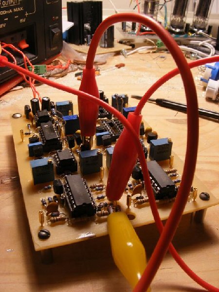
Well... The parts arived today, and the main board has been assembled.
I have completed it about an hour ago, and couldnt resist firing it up before bed. I tested only one of the two vcos, and it looks like I havent made any assembly errors. The wave shapes are fine, lin and exp fm works, the sync also seems to work.
I'll be able to test it much more tommorow, but the initial signs seem good.
There are a few strange artifacts however, such as a marked sensetivity to the presence of my finger near the saw core. Also, the triangle has a slight negative bias too it, and the gain trim doesnt apear to work.
Hopefully I can get on top of these issues tommorow.
But here is a pic of how it looks on my desk just now
| Description: |
|
| Filesize: |
83.01 KB |
| Viewed: |
377 Time(s) |
| This image has been reduced to fit the page. Click on it to enlarge. |
|
_________________
the8bitpimp.wordpress.com |
|
|
Back to top
|
|
|
Sebo
Joined: Apr 27, 2007
Posts: 564
Location: Argentina
|
|
|
Back to top
|
|
|
brother303
Joined: Nov 02, 2010
Posts: 139
Location: ruhr-area/germany
|
| Posted: Wed Apr 06, 2011 5:33 pm Post subject:
|
|
|
Hi,
Yummy!
Hope,troubleshooting will be successful. Thumbs up!
@Sebo: Don`t kill your MS... 
_________________
Best regards
Greg |
|
|
Back to top
|
|
|
Pantheon
Joined: Feb 17, 2011
Posts: 36
Location: Edinburgh
|
| Posted: Wed Apr 06, 2011 7:06 pm Post subject:
|
|
|
ok, so i've tested both sides now and they both seem to work almost identicaly which is quite a good sign.
Things of note:
- The triangle symmetry looks nice.
- The gain trim actualy works, it just doesnt have a great amount of range, but its sufficient.
- There is a very slight amount of wobble on the output of each vco (maby 100mv or less), that seems to increases with the presence of my finger by the CA3046 chip. I've had this same wobble on each version of the vco, and I havent been able to get rid of it so far. Does anyone think this will be a problem? Its not audible. I think the best I can hope for is that someone else who makes this vco might be able to figure out whats causing it. It might be present on the MS20 for all I know though.
- The saw still has to be biased a little negative for a good triangle symetry, leading to both the triangle and the saw being offset by around -500mv. I know this can be improved by changing a resistor in the triangle circuit, but its ok for my needs, so I dont think i'll change it, sry . I'll point out the resistor when I release the plans.
- Not much else to tell other than I think it sounds realy nice.
So the final thing that I need to do is to etch and test the octave and ring mod board, which I will do tommorow. Assuming that works, I'll post a PDF with the PCB for toner transfer and a small guide on how to tune it in and wire it.
Remember this will be no high end vco, I just want to emphasise that. Though hopefully once it starts getting built by people, some improvements will be suggested. For now, expect something very analoge, warm and with plenty of colour.
_________________
the8bitpimp.wordpress.com |
|
|
Back to top
|
|
|
abovenyquist
Joined: Aug 31, 2009
Posts: 55
Location: Atlanta
|
| Posted: Wed Apr 20, 2011 4:37 pm Post subject:
Trouble getting the posted VCO to work |
|
|
Dear Pantheon and other electro-music folks,
My apologies if I'm posting this in the wrong spot; I confess I don't drop in here too often. (I hang out a lot on the SDIY mailing list, but sometimes I find the many forums and topics on EM overwhelming.)
Anyway, I'm teaching my "Electronics for Music Synthesis" class again this semester:
http://users.ece.gatech.edu/~lanterma/ems11
And my students are working on their final projects. One of my suggested project ideas, which a team of two students picked, was to build your VCO (or the original Korg MS-20) sawtooth core. They're having a very difficult time, and I was hoping folks here might be able to offer some help.
They started with this schematic:
http://electro-music.com/forum/phpbb-files/xms20_vco_150.jpg
They added the JFET between the expo converter and the 10K resistor in the sawtooth core. I think you asked what this JFET was in another post; some SDIY list folks figured out the JFET is a "common gate" amplifier acting as a *current* buffer (instead of the usual voltage buffer).
After this didn't go, we figured out that the expo converter needed a reference current. So they attached a resistor (megaohm range I think) between the negative terminal of the op amp in the bottom left corner and the +15 volt rail.
They did get a sawtooth oscillation going - but it's quite high frequency (20 kHz to 40 kHz range or something like that), and very tiny (200 mV pk-to-ok or something like that). I'm wondering if these issues are related - i.e. if the "comparator" is basically tripping at the wrong point - tripping earlier than it should be - hence making the wave amplitude smaller than it should be and also have a lower period than than it should be. There's also a big DC offset that varies with the "initial tune" pot (I don't know if that's expected or not.)
In the original diagram listed above, the leftmost part of the sawtooth core has 1K and 4K7 resistors. In the SPICE diagram, these are instead 22K and 220K resistors. They've tried both; same problem, high frequency wave, tiny amplitude. They also noticed the 3906 emitter is attached to the +5 supply in the original schematic, but the 3906 collector is attached to the +5 supply in the SPICE schematic; again they've tried it both ways.
I should mention they were using a CA3083 for the NPNs, using the extra-matched pair in the expo converter, and a 2N3096 for the PNP. They used a 2N5457s for the current buffer JFET. They have the substrate pin of the CA3083 tied to the -15 V supply.
Any advice that might help towards getting this working would is greatly appreciated.
I should also mention that they've also tried to get the original Korg MS-20 VCO design working too; alas, what they have on the breadboard is not oscillating *at all*, but that's another story.
Along those lines, I noticed the Pantheon and the MS-20 VCO designs are quite different; I must confess I don't have a very good understanding of either design.
Thanks!
- Aaron |
|
|
Back to top
|
|
|
|

 Forum index » DIY Hardware and Software » Developers' Corner
