| Author |
Message |
Broadwave

Joined: Feb 16, 2007
Posts: 347
Location: Manchester UK
Audio files: 6
|
 Posted: Fri Jun 06, 2014 11:36 am Post subject: Posted: Fri Jun 06, 2014 11:36 am Post subject:
|
  |
|
| patroche wrote: | | The next is the seq ARP 1601 |
Now THAT'S something I'm definitely interested in 
If anyone can do it, you can - I gave up after 3 months (couldn't find the PCB foils) |
|
|
Back to top
|
|
 |
patroche
Joined: Feb 26, 2012
Posts: 16
Location: montelimar
|
| Posted: Sun Jun 08, 2014 11:10 am Post subject:
|
|
|
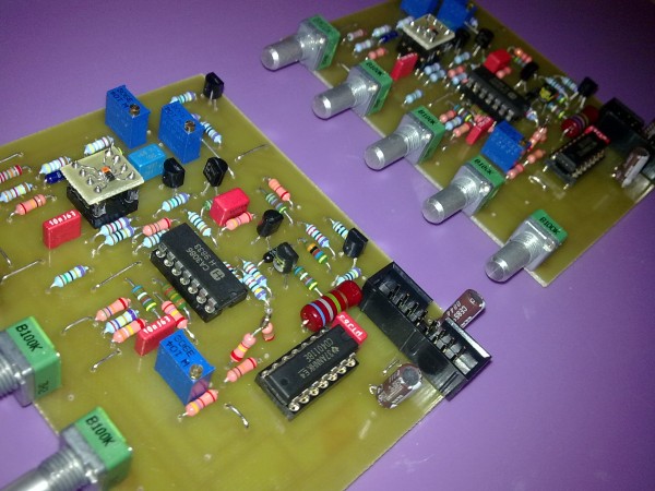
ok andy , give me your mail and i give you all my work !
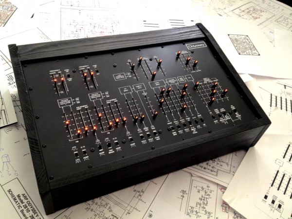
Just a picture of my project
It don't run yet , because i have many vérification , before, on the sequencer.

_________________
http://www.crazy-patroche.com/
Last edited by patroche on Sun Jun 08, 2014 9:58 pm; edited 1 time in total |
|
|
Back to top
|
|
|
Sebo

Joined: Apr 27, 2007
Posts: 564
Location: Argentina
|
| Posted: Sun Jun 08, 2014 4:32 pm Post subject:
|
|
|
WOW, the sequencer looks awesome!!!
_________________
Sebo
---------------------------------------
My Music:
https://www.facebook.com/cosaquitos/ |
|
|
Back to top
|
|
|
isak

Joined: Dec 13, 2009
Posts: 847
Location: Israel
Audio files: 18
|
|
|
Back to top
|
|
|
isak
Joined: Dec 13, 2009
Posts: 847
Location: Israel
Audio files: 18
|
| Posted: Thu Jun 19, 2014 4:00 am Post subject:
|
|
|
hi guys.
i did the Vpp boost suggested by Andy on page 8.

well, works great, i replaced the 100k to 51k and 50k trimmer so i can get it back to 10Vpp, that went out great.
as you see the signal is inverted, i want to invert it back to the original phase, i did a small scheme, someone here can please tell me if i did ok?

cheers,
Isak E.
_________________
http://www.myspace.com/mgmtrance |
|
|
Back to top
|
|
|
elmegil

Joined: Mar 20, 2012
Posts: 2179
Location: Chicago
Audio files: 16
|
| Posted: Thu Jun 19, 2014 6:16 am Post subject:
|
|
|
| I've more commonly see 10k or 20k used for the re-inverting op amp, but the layout is correct. |
|
|
Back to top
|
|
|
isak
Joined: Dec 13, 2009
Posts: 847
Location: Israel
Audio files: 18
|
| Posted: Thu Jun 19, 2014 6:53 am Post subject:
|
|
|
Thanks
So 10k to 20k instead 100k?
Ok, I'll take that in mind.
Another thing..
When looking at the scope after the Vpp boost I've noticed that the waveform is no longer from 0 to 5V, it became, (+)(-), i guess it should be like that?
I'm wandering if I wasnt connecting the -15V would it still be (+)(-)?
_________________
http://www.myspace.com/mgmtrance |
|
|
Back to top
|
|
|
elmegil
Joined: Mar 20, 2012
Posts: 2179
Location: Chicago
Audio files: 16
|
| Posted: Thu Jun 19, 2014 7:04 am Post subject:
|
|
|
2 x 10ks, or 2 x 20ks. both resistors have to be the same to have unity gain.\
It seems strange that an audio signal would be 0 - 5V; 5Vpp would normally be -2.5 to +2.5. I haven't gone back to look at the prior schematics, is there a DC blocking cap at the end of the prior stage?
In any case, don't try to run your op amp without the -15V rail. And a TL07X is not going to like simply trying to substitute ground there. You'd need a different op amp capable of doing single-sided supply. There are some LM amps (e.g. LM358) that can do that if you really feel you need to. |
|
|
Back to top
|
|
|
isak
Joined: Dec 13, 2009
Posts: 847
Location: Israel
Audio files: 18
|
| Posted: Thu Jun 19, 2014 12:16 pm Post subject:
|
|
|
hi elmegil
| Quote: | | It seems strange that an audio signal would be 0 - 5V; 5Vpp would normally be -2.5 to +2.5. I haven't gone back to look at the prior schematics |
the saw and the square are 0 to 5, in the ody vco, and 0 to 10 in the 2600 vco, this is the last time i checked.
in the 2600 vco only the Tri and Sine are (+)(-).
| Quote: | | In any case, don't try to run your op amp without the -15V rail. And a TL07X is not going to like simply trying to substitute ground there. You'd need a different op amp capable of doing single-sided supply. There are some LM amps (e.g. LM358) that can do that if you really feel you need to. |
i think you miss understand me, sorry about that.
i meant to disconnect the -15V that connected to the 300k and pin 2 of the opamp.
_________________
http://www.myspace.com/mgmtrance |
|
|
Back to top
|
|
|
elmegil
Joined: Mar 20, 2012
Posts: 2179
Location: Chicago
Audio files: 16
|
| Posted: Thu Jun 19, 2014 12:54 pm Post subject:
|
|
|
| Sorry for the misunderstanding. Seems like a good chance of it working as you say.... |
|
|
Back to top
|
|
|
isak
Joined: Dec 13, 2009
Posts: 847
Location: Israel
Audio files: 18
|
| Posted: Thu Jun 19, 2014 11:32 pm Post subject:
|
|
|
elmegil,
I don't think there is a DC block.
I guess the the -15V and the 300k is for center it around zero.
_________________
http://www.myspace.com/mgmtrance |
|
|
Back to top
|
|
|
furio

Joined: Dec 25, 2009
Posts: 124
Location: Austria
Audio files: 1
|
| Posted: Tue Jul 08, 2014 5:19 am Post subject:
|
|
|
| isak wrote: | I don't think there is a DC block.
I guess the the -15V and the 300k is for center it around zero. |
With +/-12V power supply, should the 300K be reduced by 10%, 20% or nothing? |
|
|
Back to top
|
|
|
isak
Joined: Dec 13, 2009
Posts: 847
Location: Israel
Audio files: 18
|
| Posted: Tue Jul 08, 2014 5:55 am Post subject:
|
|
|
| furio wrote: | | isak wrote: | I don't think there is a DC block.
I guess the the -15V and the 300k is for center it around zero. |
With +/-12V power supply, should the 300K be reduced by 10%, 20% or nothing? |
i was right when i said..
| Quote: | | I guess the the -15V and the 300k is for center it around zero. |
i didnt connect the -15V so there is no need for the 300k.
so it works perfect
_________________
http://www.myspace.com/mgmtrance |
|
|
Back to top
|
|
|
furio
Joined: Dec 25, 2009
Posts: 124
Location: Austria
Audio files: 1
|
| Posted: Tue Jul 08, 2014 9:08 am Post subject:
|
|
|
| isak wrote: | i didnt connect the -15V so there is no need for the 300k.
so it works perfect |
So you do not just connect the 300K or even the -15V power of the TL072? |
|
|
Back to top
|
|
|
isak
Joined: Dec 13, 2009
Posts: 847
Location: Israel
Audio files: 18
|
| Posted: Tue Jul 08, 2014 9:17 am Post subject:
|
|
|
| furio wrote: | | isak wrote: | i didnt connect the -15V so there is no need for the 300k.
so it works perfect |
So you do not just connect the 300K or even the -15V power of the TL072? |
yep
_________________
http://www.myspace.com/mgmtrance |
|
|
Back to top
|
|
|
furio
Joined: Dec 25, 2009
Posts: 124
Location: Austria
Audio files: 1
|
| Posted: Thu Jul 10, 2014 12:19 am Post subject:
|
|
|
No, I tried!
The 300K resistor seems indispensable.
It also works well with 12V.
Not installing it, simply amplify the wave without centering. |
|
|
Back to top
|
|
|
isak
Joined: Dec 13, 2009
Posts: 847
Location: Israel
Audio files: 18
|
| Posted: Thu Jul 10, 2014 2:47 am Post subject:
|
|
|
| Quote: | | Not installing it, simply amplify the wave without centering. |
this is what i wanted, this is what were talking about here.
_________________
http://www.myspace.com/mgmtrance |
|
|
Back to top
|
|
|
kanji
Joined: Aug 17, 2012
Posts: 7
Location: Finland
|
| Posted: Sun Aug 17, 2014 4:33 am Post subject:
|
|
|
Hello all. I've build several DIY synths and decided to build Odyssey using Dual Oscillator PCB.
First of all I want to thank Andy for his amazing work and dedication in this thread. Even with issues my oscs have, they sound really powerful and your work has helped a LOT to get where my project is now
I've build VCOs, Yusynths Arp filter and Yusynths VCA. ADSR/AR circuits I build from original ARP schematics, same with Mixer section, LFO and S/H.
I was happy with the raw nature the instrument has, but always thought that square waves arent as clean as they seem in odyssey videos in youtube.
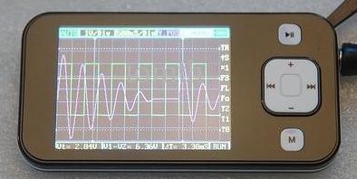
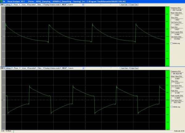
I don't have scope, but I checked both oscillators using visualanalyzer and it seems that squarewaves aren't right. Saw sounds nice and looks "ok" in analyzers screen. Squares seem to droop right after their edge has risen to peak voltage. Peak voltage doesn't stay up, instead droops before cycle starts its second half.
I'm running this on 12V and powersupply is checked and tested three times. Same goes with the PCB itself. I also tested changing 274k resistor that affects PWM but that didn't do the trick. My board sets squares dutycycle to 50/50 with original components, but squares shape is the issue.
I've used CA3146 instead of CA3086 and 2N5459's I replaced with 2N3823. All other components are like in original BOM.
If some one has any idea where to start looking solution, help would be awesome.
Thanks in advance
| Description: |
|
| Filesize: |
309.71 KB |
| Viewed: |
462 Time(s) |
| This image has been reduced to fit the page. Click on it to enlarge. |
|
| Description: |
| Saw and Square wave in Visual Analyser |
|
| Filesize: |
382.49 KB |
| Viewed: |
480 Time(s) |
| This image has been reduced to fit the page. Click on it to enlarge. |
|
|
|
|
Back to top
|
|
|
furio
Joined: Dec 25, 2009
Posts: 124
Location: Austria
Audio files: 1
|
| Posted: Sun Aug 17, 2014 7:01 am Post subject:
|
|
|
| kanji wrote: |
I don't have scope, but I checked both oscillators using visualanalyzer and it seems that squarewaves aren't right. |
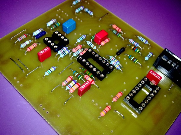
Hello kanji, nice work !!!
Respecting the descriptions of the resistors shown in the schematic... you'll get a perfect clone... respect the original scheme, it definitely will have better waves & Sound. Though it could also become very unstable, difficult to calibrate and plunder often over time the tuning.
I preferred to give up a little of musicality and increase stability to the maximum of the exponential converter and sync. Though unfortunately it is metal film, I tried anyway to use the best available Hi End Resistors.
From my tests, I noticed that a square wave acceptable, I obtained according to the schematic and placing Carbon Film Resistors at least for the waveshaper circuit.
P.S. This VCO allows +/- 0.1% tracking accuracy and stability.
| Description: |
|
| Filesize: |
632.33 KB |
| Viewed: |
477 Time(s) |
| This image has been reduced to fit the page. Click on it to enlarge. |
|
| Description: |
|
| Filesize: |
554.53 KB |
| Viewed: |
449 Time(s) |
| This image has been reduced to fit the page. Click on it to enlarge. |
|
|
|
|
Back to top
|
|
|
Sebo
Joined: Apr 27, 2007
Posts: 564
Location: Argentina
|
| Posted: Mon Aug 18, 2014 10:31 am Post subject:
|
|
|
The squares look like that because you are using a sound card to get the audio into the computer for analizing it. The sound card have a high pass filter to block DC, and that HP filter is deforming the waves.
If you use a real oscilloscope or get hold of a sound card without the high pass filters (there are a few of them, MOTU for example) you would see an almost perfect square.
_________________
Sebo
---------------------------------------
My Music:
https://www.facebook.com/cosaquitos/ |
|
|
Back to top
|
|
|
furio
Joined: Dec 25, 2009
Posts: 124
Location: Austria
Audio files: 1
|
| Posted: Mon Aug 18, 2014 1:12 pm Post subject:
|
|
|
| Sebo wrote: | The squares look like that because you are using a sound card to get the audio into the computer for analizing it. The sound card have a high pass filter to block DC, and that HP filter is deforming the waves.
If you use a real oscilloscope or get hold of a sound card without the high pass filters (there are a few of them, MOTU for example) you would see an almost perfect square. |
The use of the correct types of resistors as schematic, would have always been crucial to mitigate the distortion of the square. As well as exact types with little bandwidth (low noise) deforms the waves.
Whether the worst converters can accentuate the problem, would be another interesting question..
This would be the schematic: 5% & 10% = Carbon Film / = 1% Metal Film.
http://electro-music.com/wiki/pmwiki.php?n=Schematics.ARPOdysseyMKII-IIIVCO |
|
|
Back to top
|
|
|
Sebo
Joined: Apr 27, 2007
Posts: 564
Location: Argentina
|
| Posted: Mon Aug 18, 2014 3:31 pm Post subject:
|
|
|
The converters have nothing to do. The problem are the High Pass Filter that blocks the DC at the input of the sound card.
Just look at the waves with a proper oscilloscope and you will see the diference.
It's funny, this subject is popping out again and again. Software oscilloscopes aren't good for some tasks because the DC blocking filters of the sound cards. You can't measure DC offset (to calibrate a VCA for example), you can't properly see an LFO, and waveforms of VCO will be deformated, specially in lower frequencies...
_________________
Sebo
---------------------------------------
My Music:
https://www.facebook.com/cosaquitos/
Last edited by Sebo on Tue Aug 19, 2014 4:04 pm; edited 1 time in total |
|
|
Back to top
|
|
|
Broadwave
Joined: Feb 16, 2007
Posts: 347
Location: Manchester UK
Audio files: 6
|
|
|
Back to top
|
|
|
kanji
Joined: Aug 17, 2012
Posts: 7
Location: Finland
|
| Posted: Wed Aug 20, 2014 12:51 pm Post subject:
|
|
|
Thanks guys for the help and info. What drow me to take a look more closely to the waveforms was an interference/sidenoise that could be heard on both oscillators. I thought that its a side product of wrong shaped wave. Like square mixed with little bit of saw wave. This side noise reacted to pitch so I thought it must have something to do with the shape of square wave.
Later I noticed that I forgot to solder in 10uf decoupling caps and when those didn't eliminate the issue, I added 100n caps to powerrails aswell.
Funny though, while I googled info about oddys square waves and known issues, I stumbled on this 
http://www.gearslutz.com/board/electronic-music-instruments-electronic-music-production/778218-arp-odyssey-wonky-square-waves.html
EDIT : Got it working.. problem was most embarrassing.. Oscillators sounded great when I tested those out from the synth, but when I installed PCB back in, side noise came back. I started to hook modules one by one to powersupply until sidenoise appeared. Problem was that my powersupplys caps were bit too small for the load all these modules take. I boosted in total more than 10000uf more to my PSU and now everything works great.
Thanks again Andy for sharing your work
Here is a small clip how my oddy clone sounds. All sounds (apart white noise) made using these oscillators.
https://soundcloud.com/tiergrinder/clockwork-odyssey |
|
|
Back to top
|
|
|
krainov
Joined: Feb 26, 2015
Posts: 20
Location: Nowhereland
|
| Posted: Sun Jul 05, 2015 1:47 pm Post subject:
VCO 1 Audio/LF Switch? |
|
|
Hello!
Could anyone tell me what is VCO 1 Audio/LF Switch on the pcb? |
|
|
Back to top
|
|
|
|

 Forum index » DIY Hardware and Software