| Author |
Message |
ulrich.audio
Joined: Jul 13, 2015
Posts: 1
Location: bremen, germany
|
 Posted: Sat Jul 02, 2016 4:08 am Post subject:
interfering sound generators?? since new PSU Posted: Sat Jul 02, 2016 4:08 am Post subject:
interfering sound generators?? since new PSU
Subject description: lfo modulate vco freq without being patched |
  |
|
hi there,
i got some weird situation here, i just build the MFOS adjustable PSU (LM317,337) for my yusynth system - running on +/-15v
it seems like the smoothing caps are way to small to supply the hole system (20 modules) but thats another point i think
so i started to plug one module after another to see when the psu starts failing
when i plugged in a vco first it worked well - then i plugged in one of the lfos the vco's pitch started modulating in the lfo's rate without anything being patched
this problem only appears with the mfos supply - on my old 12v psu wich is just two dc wall warts connected together nothing interferes like this
has anyone similar experiences with the mfos supply?? or an idea how this can happen at all
cheers
ulli |
|
|
Back to top
|
|
 |
alanwilder81
Joined: Sep 03, 2016
Posts: 310
Location: italy
|
| Posted: Wed Dec 28, 2016 2:06 pm Post subject:
|
|
|
man, i had the same exact issue as yours.
i use a 250 mA dual PSU.
It had a simple VCO loaded. I added and powered an lfo to the same PSU, and without even connecting the lfo to the VCO, the latter started to wobble and go up and down in pitch.
I couldnt find any explanation nor anyone experimenting that crap until i came across your post.
And after powering the LFO from a separate PSU the problem disappeared at all. What the hell is that?  |
|
|
Back to top
|
|
|
blue hell
Site Admin

Joined: Apr 03, 2004
Posts: 24422
Location: The Netherlands, Enschede
Audio files: 297
G2 patch files: 320
|
| Posted: Wed Dec 28, 2016 4:19 pm Post subject:
|
|
|
This is another example of where the circuit is not what you think it to be.
Usually a power supply is assumed to be perfect, in that it will give a steady constant output voltage no matter what the load is. In that case it can be seen as independent from the circuits that are powered from it.
However nothing is perfect in this world. What happens is that one module will load the power supply unevenly causing it's output voltage to change. The changing output voltage will then affect the other module. And this makes the circuit more complex, in that the power supply has become part of the circuit.
Basically this is pretty simple to solve by making the power supply better. So the question becomes what is a good power supply, and that one is a bit less simple to answer here in a handful of lines.
I know there to be a power supply design thread somewhere on this forum ... let me see ... ok, two :
http://www.electro-music.com/forum/topic-51631.html
http://electro-music.com/forum/topic-51694.html
_________________
Jan
also .. could someone please turn down the thermostat a bit.
 |
|
|
Back to top
|
|
|
alanwilder81
Joined: Sep 03, 2016
Posts: 310
Location: italy
|
| Posted: Wed Dec 28, 2016 4:50 pm Post subject:
|
|
|
hey Blue Hell,
thanks for the fast reply 
and for the detailed and articulate explanation of what it's likely to be happening!
i am now going to read the discussions you linked me to.
As little as i know about EE, it's quite clear, by now, that building a proper PSU is unavoidable. I've been screwing around with modules and experimenting, but it's high time to get things done properly now.
I'll come back to you when i read those topics to further comment.
thanks again! |
|
|
Back to top
|
|
|
wackelpeter
Joined: May 05, 2013
Posts: 461
Location: germany
Audio files: 10
|
| Posted: Thu Dec 29, 2016 2:09 am Post subject:
|
|
|
As i guess most of your LFO's and a lot other circuits have LED's it's a good choice to use low current LED's (2mA) therefore and increase the resistors for the LED's until the best result in current limiting is reached and they're bright enough...
But still a 250mA PSU is only a solution for a tiny amount of modules...
Can also recommend to read the issue of Electro Notes which gives a lot of details and tips on PSU's. It's available online as free pdf download.
_________________
https://soundcloud.com/bastian-j |
|
|
Back to top
|
|
|
alanwilder81
Joined: Sep 03, 2016
Posts: 310
Location: italy
|
| Posted: Thu Dec 29, 2016 3:52 am Post subject:
|
|
|
thanks wackelpeter !
and yes,my PSU,rated for 250 mA is only fit for testing very few modules at a given time, and even then, it craps out as soon as the load increases 
what would it be an ideal PSU amperage to drive ,say, a small modular synthesizer ?
I seem to grasp it should be at least 1.5 A.
in a nutshell, is the amperage the only parameter to care about in building a decent PSU to avoid overload issues like mine? sure there's a lot more to be considered ,like voltage stability,proper hum filtering and so on 
thanks! |
|
|
Back to top
|
|
|
blue hell
Site Admin
Joined: Apr 03, 2004
Posts: 24422
Location: The Netherlands, Enschede
Audio files: 297
G2 patch files: 320
|
|
|
Back to top
|
|
|
wackelpeter
Joined: May 05, 2013
Posts: 461
Location: germany
Audio files: 10
|
| Posted: Thu Dec 29, 2016 4:16 am Post subject:
|
|
|
For a small/medium cabinet i would go for at least 1A...
But the problem with your VCO is maybe at some point related to your PSU but also a lot on what is hooked upon it too...
Like i said some of the schematics around mostly indicating 1k current limiting resistors for LED's gave me 10-20mA flowing through the LED... This causes small Voltage drops in the PSU of a few mV but it's in most cases enough that you hear how your pitch changes as the LED goes on and off...
Optimizing your circuits that you have an almost/nearly constant/equal current flowing, by minimizing for example the current of the LED's is the best thing to start without having much to overwork again...
I usually when finishing a circuit do put in a multimeter in the line of the LED and measure the current, by adjusting the resistor and looking if it's bright enough i mostly end up with something like 2mA down to a 0,6mA...
With the original/usual 1K resistor the current was much higher as stated above.
Also noteworthy is to use for trigger/sequencing stuff separate PSU's as for filters and VCO'S...
Like i had in my bigger cabinets... One PSU for the various dividers, sequncers, brust generators and gate to trigger dividers and the other for the "musical" stuff like VCO,Slopes,VCF,VCA and so on...
_________________
https://soundcloud.com/bastian-j |
|
|
Back to top
|
|
|
blue hell
Site Admin
Joined: Apr 03, 2004
Posts: 24422
Location: The Netherlands, Enschede
Audio files: 297
G2 patch files: 320
|
| Posted: Thu Dec 29, 2016 4:24 am Post subject:
|
|
|
| alanwilder81 wrote: | | in a nutshell, is the amperage the only parameter to care about in building a decent PSU to avoid overload issues like mine? sure there's a lot more to be considered ,like voltage stability,proper hum filtering and so on :roll: :roll: |
The voltage before the regulators could be too low, making it hard for the regulators to regulate. This boils down to using a transformer with a high enough voltage output. But - you do not want it to be too high, as that would result in needlessly hot regulators / large heat sinks.
This seems to be a common mistake.
_________________
Jan
also .. could someone please turn down the thermostat a bit.
|
|
|
Back to top
|
|
|
blue hell
Site Admin
Joined: Apr 03, 2004
Posts: 24422
Location: The Netherlands, Enschede
Audio files: 297
G2 patch files: 320
|
| Posted: Thu Dec 29, 2016 4:29 am Post subject:
|
|
|
Another thing would be to connect the modules in a star like topology (connect each module to the power supply separately), and to not chain the power lines from one module to the next.
_________________
Jan
also .. could someone please turn down the thermostat a bit.
|
|
|
Back to top
|
|
|
wackelpeter
Joined: May 05, 2013
Posts: 461
Location: germany
Audio files: 10
|
| Posted: Thu Dec 29, 2016 4:49 am Post subject:
|
|
|
Would second Jan's words... Especially those with the overheated regulators...
...and the link for the PSU is also a goog advice for an quality PSU.
The total current isn't the only thing to look after, as long as it's in the limit of the PSU and i would like to add that it's better to leave some headroom and to not connect endless amount of modules to it where it's always running on it's limit... what i wanted to tell is that the more load/current you drwa from your PSU the more would changes in the current you draw from it affect the output voltage... so try to keep the current consumption as stable as possible...
Regarding the input caps before the regulators you should be fine as long as they provide at least 17V to the regulator input... when doing a board maybe keep in mind to safe some space or extra place to add some Caps or use a bigger instead...
The EN article also gives some examples for different cap sizes for different transformator values.... and so on
_________________
https://soundcloud.com/bastian-j |
|
|
Back to top
|
|
|
alanwilder81
Joined: Sep 03, 2016
Posts: 310
Location: italy
|
| Posted: Thu Dec 29, 2016 5:11 am Post subject:
|
|
|
wow
i owe you guys a beer, or a nice italian wine if you come to town 
you are being immensely helpful.
that's spot on, wackelpeter! clear explanation, now it's time for me to delve into some theory, and learn in dept what a transformer does, what a bridge rectifier does, as well as the big role played by capacitors and most importantly, safety rules !
i always overlooked the importance of a good PSU.
sure, making VCO s and low pass filters is much more fun  ,but hey, they wont work if there's not a goos PSU to feed 'em. ,but hey, they wont work if there's not a goos PSU to feed 'em.
thanks for the support,i need to study lots now |
|
|
Back to top
|
|
|
alanwilder81
Joined: Sep 03, 2016
Posts: 310
Location: italy
|
| Posted: Thu Dec 29, 2016 5:27 am Post subject:
|
|
|
thanks jan,
i just took a look at the Thomas Henry PSU. Once again the wonderful man delivers ! May i just go for that project ?
most of my modules work with + - 12 V.
i wonder if i can use the LM 317 and LM 337 to regulate the voltage in place of the 7815 and 7915 Thomas specifies in his circuit !
cheers |
|
|
Back to top
|
|
|
wackelpeter
Joined: May 05, 2013
Posts: 461
Location: germany
Audio files: 10
|
|
|
Back to top
|
|
|
alanwilder81
Joined: Sep 03, 2016
Posts: 310
Location: italy
|
| Posted: Thu Dec 29, 2016 8:52 am Post subject:
|
|
|
thanks wackelpeter !
holy crap that's a goldmine ! |
|
|
Back to top
|
|
|
alanwilder81
Joined: Sep 03, 2016
Posts: 310
Location: italy
|
|
|
Back to top
|
|
|
wackelpeter
Joined: May 05, 2013
Posts: 461
Location: germany
Audio files: 10
|
| Posted: Thu Dec 29, 2016 2:22 pm Post subject:
|
|
|
Don't really got what you're meaning. Do you hear some pitch changes in your VCO when the LED goes on and off?
As long as you don't have any pitch changes there is no real need for a cure...
But i might add, that if you have a few of these blinking lights around your cabinet the currents add to each other and the sum then could cause some voltage drops which might be audible...
I for example would just hook a multimeter in the path between the resistor and the anode of the LED and would measure what current it draws when at brightest state. (As i don't have this module here i cannot say if there's much room to get it lightning with lower current consumption. It also depends on if you're using low current LED or a normal LED)
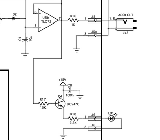
Then if i think there's some room to get lower i would try to add a small 10-50k pot in series and play around with it until i have some better results (with lower current) and the LED still matches the state of the ADSR.
Maybe it's useful to use low current LED's in general as they only need roughly 2mA because normal LED's need a lot more... Don't know what kind of LED's you're using but when those are normal LED's maybe there's little room to minimize the current...
BTW. at my retailer 5mm 2mA LED's do cost the same as the "normal" ones and the brightness is a bit less but i always managed it to get them blinking bright enough and still drawing minimal amount of current.
_________________
https://soundcloud.com/bastian-j |
|
|
Back to top
|
|
|
alanwilder81
Joined: Sep 03, 2016
Posts: 310
Location: italy
|
| Posted: Thu Dec 29, 2016 2:55 pm Post subject:
|
|
|
thanks wackelpeter,
well, i haven't experimented a pitch fluctuation on my VCO . My ADSR has a "regular" LED. However, you grabbed my attention when you mentioned the low current LED's (which i didn't know about) ,or the nice trick of placing a resistor in series (after measuring current and playing around with the pot as you describe). I am interested,obviously,in whatever trick is there to keep the modules current drawing as low as possible, hence my quest for "a cure".
excuse my rough english by the way, its not an easy thing to actually talk about EE in another language . Hope you understand my point now
cheers |
|
|
Back to top
|
|
|
wackelpeter
Joined: May 05, 2013
Posts: 461
Location: germany
Audio files: 10
|
| Posted: Fri Dec 30, 2016 1:22 am Post subject:
|
|
|
Think i finally got it now... Took me a while since in my brain only flow creeping currents and they're slooooowwww......
Having the overall current consumption in sight and avoiding greater peaks in current, which under certain circumstances can force the PSU to be unstable, isn't the badest idea...
Therefore, i hope someone with more knowledge can confirm or this or say that i'm wrong, in certain applications it's a good idea to swap in for the TL07x IC's either of the TL08x,05x or 06x series as, i don't remember exactly which of them, one of those is the low power version of those TL series IC's which demands only a small fraction of current as the other TL series... okay got it, it was the TL06x series...
200uA per channel against 1,4 to 2,2mA per channel for the others...
Performance wise they are not equally the same and as far as i remember have some lower specs, compared to the others, but in some cases where you don't need super fast slew rates or something like that, they would do the job too...
And here also the sum makes the difference... 10x TL074 1,4mAx40=56mA vs. 10xTL064 200uAx40=8mA
I am right, anyone who can confirm this?
_________________
https://soundcloud.com/bastian-j |
|
|
Back to top
|
|
|
alanwilder81
Joined: Sep 03, 2016
Posts: 310
Location: italy
|
| Posted: Fri Dec 30, 2016 1:33 am Post subject:
|
|
|
hello wackelpeter
it's early morning here in italy, as well as in germany i suppose ,so it's hard to do the maths at this time of the day
so, different op amps can add or take to the overall current consumption, so that's another aspect to be considered.
I personally use the TL 074 or TL 084, i always go for the quad op amps because of convenience.Cheaper then,say, 4 single TL071, less wiring involved and less space taken up.
As far as specs,well, i cant contribute that much to the discussion. Let's wait for the more knowledgeables to join the topic lol |
|
|
Back to top
|
|
|
alanwilder81
Joined: Sep 03, 2016
Posts: 310
Location: italy
|
| Posted: Fri Dec 30, 2016 1:41 am Post subject:
|
|
|
i'd like to ask you a dumb question, sound quality wise.
Using the above mentioned TL074 or TL084 workhorses pratically on every VCO i've made, i noticed that they more or less sound the same.
Is the op amp the main contributor to the overall VCO charachter and flavor ?
|
|
|
Back to top
|
|
|
wackelpeter
Joined: May 05, 2013
Posts: 461
Location: germany
Audio files: 10
|
| Posted: Fri Dec 30, 2016 10:26 am Post subject:
|
|
|
There are no dumb questions...
The main "character" of a VCO is by my thoughts, based on it's core (saw/triangle) and the waveshapers...
Regarding the OPamps used in VCO's or something else there is no way to tell you what's the best "soundwise"...
Well, some circuits need a specific sort of OPamp with the correct specifics and in some circuits it depends on the listeners/musicians taste...
Like some of us prefer clean/high-end sounds others prefer dirty/lo-fi sounding things and some are stuck in between...
Amps like the A741 are really vintage, whilst TL071 are some kind of universal Opamp and at least you have the high-end amps from Burr-Brown OPA...
Each of them has different characteristics with the last mentioned almost perfect from an engineers point of view, but as in real life total precision or perfection can for some become a bit boring. Like a pure triangle sounds a bit "clean and cold" with some overtones or a bit deranged it "becomes alive"... It's more a matter of your own perception and discussing such things is also more of a theoretical and philosophical nature...
I would go first with the recommended OPamps(as long as they aren'T obsolete) as per schematics to check the whole circuit is running as desired and then maybe change some of the socketed IC's to see if i can improve things or make things worse and maybe the latter would not worry me as it gives some new exciting flavour to my circuit...
_________________
https://soundcloud.com/bastian-j |
|
|
Back to top
|
|
|
alanwilder81
Joined: Sep 03, 2016
Posts: 310
Location: italy
|
| Posted: Fri Dec 30, 2016 11:36 am Post subject:
|
|
|
to wackelpeter
Yes, absolutely agreed ! Not always the "best looking" waveforms sound better, nor the "best specs amp in town" delivers our favourite sound.
i like to mention the ubiquitous LM741, the very first amp i ever employed.
And yes, the triangle and square it's able to output are fat,thick, deep, alive, rich, dirty. All there's to love about an analog signal. Yet, specs wise it's almost laughable by today s standards.
Wish i could find some LM741 from my italian supplier, but he says it's obsolete and not n stock  |
|
|
Back to top
|
|
|
alanwilder81
Joined: Sep 03, 2016
Posts: 310
Location: italy
|
| Posted: Fri Dec 30, 2016 11:39 am Post subject:
|
|
|
moreover, find the TL 071 and TL series in general kinda rubbery, but sterile in comparison. But they are cheap  |
|
|
Back to top
|
|
|
alanwilder81
Joined: Sep 03, 2016
Posts: 310
Location: italy
|
| Posted: Sat Dec 31, 2016 9:18 am Post subject:
|
|
|
happy new year to everybody !  |
|
|
Back to top
|
|
|
|

 Forum index » DIY Hardware and Software » YuSynth