| Author |
Message |
zipzap
Joined: Nov 22, 2005
Posts: 559
Location: germany
Audio files: 24
|
 Posted: Wed Apr 12, 2006 1:29 pm Post subject:
Heavy metal with xors Posted: Wed Apr 12, 2006 1:29 pm Post subject:
Heavy metal with xors |
  |
|
just got this from an old book. Looks fun so i want to tell you.
They call it heavy metal machine. It should sound like cymbals or banging against the body of a ship.
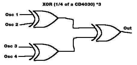
Take 4 indepandant square oscillators, send each two into an cmos-exor gate, send the two exors into a third exor. (hope that was clear)
than process with vcf/vca/adsr.
Haven´t tried it yet, my workbench is so full i can´t touch anything.
Should be nice with voltage controll for the square generators. Maybe just for one or two of them.
Maybe at slow speed this can create interresting trigger patterns.
cheers |
|
|
Back to top
|
|
 |
bugbrand

Joined: Nov 27, 2005
Posts: 846
Location: Bristol, UK
Audio files: 1
G2 patch files: 1
|
| Posted: Wed Apr 12, 2006 2:46 pm Post subject:
|
|
|
Yes it does make ACE sounds - there's quite a few little variations possible and a few designs around - actually this is kind of the heart of quite a few noise boxes I've made with the addition of body contact points into the osc & ring mod circuits. I've used 40106 to make simple sqr wave oscs (vactrol pitch CV control can be used) feeding into 4070 or 4077 - hey, starving these chips of power (circuit bend low power mod) can be quite damn fine. Mmmm you some really beautiful drone tones from such devices.
Sure there's one somewhere in Cloned Analogue Gear or maybe it was something like the Syn-are or Syn-bal...
_________________
http://www.bugbrand.co.uk
http://www.bugbrand.blogspot.com |
|
|
Back to top
|
|
|
zipzap
Joined: Nov 22, 2005
Posts: 559
Location: germany
Audio files: 24
|
|
|
Back to top
|
|
|
piedwagtail

Joined: Apr 15, 2006
Posts: 297
Location: shoreditch
Audio files: 3
|
| Posted: Fri May 26, 2006 10:07 pm Post subject:
|
|
|
Nice sample Zipzap,enjoyed that.Especially the rhythmic fluctuations.....
Robert |
|
|
Back to top
|
|
|
Scott Stites
Janitor


Joined: Dec 23, 2005
Posts: 4127
Location: Mount Hope, KS USA
Audio files: 96
|
| Posted: Sat May 27, 2006 7:19 am Post subject:
|
|
|
Pretty cool, indeed!
Cheerios,
Scott |
|
|
Back to top
|
|
|
dnny

Joined: Mar 12, 2005
Posts: 519
Location: Helsinki, Finland
Audio files: 8
|
| Posted: Sat May 27, 2006 10:18 am Post subject:
|
|
|
great. i have to try this at home - when i have some time
_________________
Association of experimental electronics
www.koelse.org
flickr: cable porn group |
|
|
Back to top
|
|
|
toppobrillo

Joined: Dec 10, 2005
Posts: 766
Location: oakland, ca
G2 patch files: 1
|
| Posted: Sun May 28, 2006 6:01 am Post subject:
|
|
|
| cool. i love sound samples. they've always been a real pain for me to do, but now i have an easy program [but the shit-of-shit for soundcard] so i look forward to posting some here. |
|
|
Back to top
|
|
|
bugbrand
Joined: Nov 27, 2005
Posts: 846
Location: Bristol, UK
Audio files: 1
G2 patch files: 1
|
| Posted: Tue May 30, 2006 2:08 am Post subject:
|
|
|
Yes Ace Sound Joy!
For low power I just starve the digital chips by placing a 1M lin pot across the power line (but only the power for the digital chips!). At low resistances this works pretty much as a tune control, but things go wierdy at high resistance (where power is really starved) - the only thing I think to watch / be aware of is that 'cos the chips are getting low supply voltage, the output waveforms have a lower amplitude ('cos they swing from gnd to +ve supply voltage) -- so 'volume' (level) goes down when the chips are starved.
_________________
http://www.bugbrand.co.uk
http://www.bugbrand.blogspot.com |
|
|
Back to top
|
|
|
zipzap
Joined: Nov 22, 2005
Posts: 559
Location: germany
Audio files: 24
|
| Posted: Tue May 30, 2006 7:19 am Post subject:
|
|
|
| Maybe we could use a dual Pot with some aditional resistors. One half starving the chip, one half controlling volume. I´m gonna try and check this out. I also thought of voltage controlling the starving with an opamp powering the cmos chips. Maybe it´s fun, maybe not really. |
|
|
Back to top
|
|
|
zipzap
Joined: Nov 22, 2005
Posts: 559
Location: germany
Audio files: 24
|
| Posted: Wed May 31, 2006 4:30 am Post subject:
|
|
|
Just gave it a try. this is fun!
Slight modulation of the power sounds really great with changing overtones, at very low level i get just clicks, sometimes random, sometimes in a cool pattern. good for clocking, triggering, whatever.
About the volume: Even when starving the chip, we are still dealing with logic square pulses here, right?
So it might work to have some comparator thing to get an even output voltage (should be dividet down of course).
Right now i have a tl084 as an voltage buffer out for osc 1+2, 3+4, 1+2+3+4 and 4 (can make cool stereo sounds that way). All i have to do is disconnect the inv. input from the output and put it to ground instead. Am i right there or do i miss something?
Then next i´ll see if this sounds the same when a opamp is used to power the cmos chips. Power should be no problem, since it´s only two chips, but i guess i have to do something so that the voltage can´t go negativ.
I don´t think the chips would like that. |
|
|
Back to top
|
|
|
piedwagtail
Joined: Apr 15, 2006
Posts: 297
Location: shoreditch
Audio files: 3
|
| Posted: Wed May 31, 2006 10:23 am Post subject:
|
|
|
Zipzap,
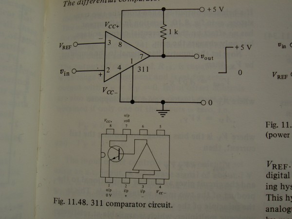
Can i be so impolite ,here,as to introduce the LM311 comparator chip?
I do believe it could be an asset to you.
Whilst there are chips with 4 comparator blocks,LM339,what is nice about the LM311,apart from being priced cheaply,is the backend.
As your dilemmas of the current droop from last month are still in my mind,this little chip has a medium power transistor on the output,in fact it is a fireblower,pushing up to 50mA.
It can handle between +/- 17V on 18Vpower rails on the input .And can have the output transistor supplied off a different supply,so it could just fire out 5V if required.
I have enjoyed the pin 1 and pin4 to -15V,pin 3 ref,pin2 input,pin8 +15,pin7 is output and collector and as such is tied up to 15V with 1K.(Take it to 5V for etc.)
I don't imagine you'll need it here,but perhaps those event timers over at Peter Grenders might set you off....
Robert |
|
|
Back to top
|
|
|
zipzap
Joined: Nov 22, 2005
Posts: 559
Location: germany
Audio files: 24
|
| Posted: Wed May 31, 2006 1:41 pm Post subject:
|
|
|
Hi Robert. Don´t worry, even if it was inpolite i wouldn´t mind a bit.
The Chip you mention sounds useful. That output transistor must be good for interfacing logic signals. Very good to know about!
In this case i also think it´s not needed because - the tl084 output opamp is already on the board - i don´t want to redesign, just do some nasty-type reconnecting. I´m a lazy person.
Also i once heard that special comperators are only needed if you want very high speed. Since we are no bats i think old 084 will be ok.
But who is Peter Grender? |
|
|
Back to top
|
|
|
piedwagtail
Joined: Apr 15, 2006
Posts: 297
Location: shoreditch
Audio files: 3
|
| Posted: Thu Jun 01, 2006 12:31 am Post subject:
|
|
|
Peter Grenader 
spelling!
http://www.buzzclick-music.com/
specifically...http://www.buzzclick-music.com/homebrew.html
he's an interesting west coast composer,synth-builder,behind some of the ear group designs,the man of Milton,and currently unpleased about appropriation of his work by Cyn industries.
i've appropriated the joystick,voltage processor,low pass gate,sample and hold which all
work wondrously.He's as important as Thomas Henry to my construction.
second
i must have been tired...
the pin 1 of the 311,goes to 0v,7 is pulled up to +15 or +whatever gate you want.that sets the output range,pin 4 can go to 0v if you are comparing above ground or to -15V etc for zero detection etc.
er...that needs a photo now...
(my digcamera is excelling itself for some reason)
Robert
| Description: |
|
| Filesize: |
282.58 KB |
| Viewed: |
718 Time(s) |
| This image has been reduced to fit the page. Click on it to enlarge. |
|
|
|
|
Back to top
|
|
|
bugbrand
Joined: Nov 27, 2005
Posts: 846
Location: Bristol, UK
Audio files: 1
G2 patch files: 1
|
| Posted: Thu Jun 01, 2006 1:54 am Post subject:
|
|
|
Hey Robert - mighty thanks for pointing towards Peter Grenader's site - I'd heard of him many times but never actually seen the site and there's really great circuits there. ACE IN EXTREMIS.
...hmmm, I've always just had the logic chips pretty much unbuffered (though may be good at the output) -- and just thought that a simple way to get around the amplitude drop problem would be to put the signal through another invert buffer like you're using for the original squarewave oscs..?.. (..I'm often only using a couple of the hex-inverter gates, so using up an extra one would be easy..)
_________________
http://www.bugbrand.co.uk
http://www.bugbrand.blogspot.com |
|
|
Back to top
|
|
|
zipzap
Joined: Nov 22, 2005
Posts: 559
Location: germany
Audio files: 24
|
| Posted: Thu Jun 01, 2006 4:37 am Post subject:
|
|
|
This site is great! I´ve been there once, but hadn´t noticed how cool those circuits are! That delay seems great. i have to go for it!
Useing another inverter might not work when you drop the voltage below half the supply voltage, which as far as i know is the minimum level for a high signal. So a comperator is propably the right way.
I just added the buffer because i always do that. As long as you just drive some high impedance (buffered) input it´s not really needed. 1k at the output of the cmos chip is propably enough to protect it against overload anyway. |
|
|
Back to top
|
|
|
zipzap
Joined: Nov 22, 2005
Posts: 559
Location: germany
Audio files: 24
|
|
|
Back to top
|
|
|
fldrvr
Joined: Jul 13, 2006
Posts: 33
Location: USA
|
| Posted: Mon Jul 31, 2006 11:56 am Post subject:
|
|
|
Is this a stand-alone device or part of a module?
Can you post a schematic or a link- I'm not seeing it. Sounds great. |
|
|
Back to top
|
|
|
Mikmo
Joined: Dec 01, 2005
Posts: 150
Location: Copenhagen - Denmark
|
| Posted: Mon Jul 31, 2006 2:20 pm Post subject:
|
|
|
Ahh i finally breadboarded one of these.
I build it with 2 joysticks controlling the pitch of the 4 squarewaves.
My joysticks have only 10K pots, i would have liked 100 or 150, but the sounds are cool. When i build the final version i think i will put slideswitches with little banks of different capacitors for each oscillator.
those of you who have build one should try to put a solar cell (NOT a photoresistor) in series with the supply voltage. The frequency of the oscillators are depending on the supplyvoltage, so you can "modulate" all 4 oscillators by moving your hand in front of the solar cell. The credit for the solar cell trick goes to the guts from Chromatic Field and their solar modules check it here: http://www.sciss.de/chromaticfield/texts/modules.html
What value potentiometers and caps are you all using ?
_________________
Stay Cool
Mikael
http://www.mikmo.dk |
|
|
Back to top
|
|
|
zipzap
Joined: Nov 22, 2005
Posts: 559
Location: germany
Audio files: 24
|
| Posted: Tue Aug 01, 2006 2:35 am Post subject:
|
|
|
| Quote: | Is this a stand-alone device or part of a module?
|
fldrvr, hard to tell... It´s a module, part of a synth, by itself not that useful.
If you read the first post you´ll find the description how the sound is generated. If you can´t follow tell me, i´ll paint a napkin.
But anyway that´s only what makes the noisy sounds (all the time). So as a standalone unit you want at least a simple vca, (hand-)trigger and decay envelope.
The sound examples were made with a sequencer controlling pitch and gate.
Hey mikmo, hope you´re having fun with this. Joystick sound´s perfect. If you still got it on breadboard try controlling two of the oscs with indeoendand ldrs. i loved that. Have to check that solar cell stuff. I´ll read the link you posted.
Although i´m not sure, i belive the supply voltage doesn´t affect the speed that much if you use cmos-gate oscillators. It´s something different happening, makeing them just go weird. Anyway that doesn´t matter, if it sounds right...
I´m using 500k and 1meg pots. i put the ldr in series to the pots, in other words: it doesn´t matter what you do. Cabs are around 10-100n i think. Those 10k pots are a bit low, if you don´t mind the extra work you could use the joysticks to controll 4 vactrols with high resistance range.
Or maybe just a larger cab will give you god range.
_________________
http://www.myspace.com/lorolocoacousticpop
http://www.myspace.com/petrolvendor
music and transcribed jazz basslines |
|
|
Back to top
|
|
|
Uncle Krunkus
Moderator

Joined: Jul 11, 2005
Posts: 4761
Location: Sydney, Australia
Audio files: 52
G2 patch files: 1
|
| Posted: Tue Aug 01, 2006 4:25 am Post subject:
|
|
|
Yeah, just up the caps. I'm not sure about God range, but it should help alot! 
_________________
What makes a space ours, is what we put there, and what we do there. |
|
|
Back to top
|
|
|
fldrvr
Joined: Jul 13, 2006
Posts: 33
Location: USA
|
| Posted: Tue Aug 01, 2006 6:32 am Post subject:
|
|
|
Well.. honestly it is a bit above my head and the project sounds advanced for my currently meager abilities. I'm sure that any explanation you offer would help out everyone, though.
Thanks! |
|
|
Back to top
|
|
|
Uncle Krunkus
Moderator
Joined: Jul 11, 2005
Posts: 4761
Location: Sydney, Australia
Audio files: 52
G2 patch files: 1
|
|
|
Back to top
|
|
|
zipzap
Joined: Nov 22, 2005
Posts: 559
Location: germany
Audio files: 24
|
| Posted: Tue Aug 01, 2006 12:07 pm Post subject:
|
|
|
exactly. so any of the oscs from your other post will work. It´s also possible to use the outputs of the first exor gates. They sound different, less complex.
Don´t worry, this is not as advanced as the sound it produces, so you´ll manage.
An exor is a special type of logic gate. Like the and gate and all the others. Check your library for the cmos cookbook by don lancaster. This was all above my head till i read that book (3 times).
So you have two square oscs. What do they do? Turn on and off. Thats high or low - 1 or 0. Thats digital logic signal. So it can be prozessed with logic gates. xor means exclusive-or. The 4030 is one of those. That means the gate compares it´s two inputs. If they are different it´s output goes high. In all other cases the output stays low. So you get a complex(sounding) pattern out of the even on/off of the square oscs.
In this case you do the whole thing twice and send the outs to a third exor. Makes it even more complex. To start with you can try the whole thing with 2 square oscs and 1/4 of the 4030. Then build up the rest. Can you follow?
_________________
http://www.myspace.com/lorolocoacousticpop
http://www.myspace.com/petrolvendor
music and transcribed jazz basslines
Last edited by zipzap on Tue Aug 01, 2006 12:12 pm; edited 1 time in total |
|
|
Back to top
|
|
|
zipzap
Joined: Nov 22, 2005
Posts: 559
Location: germany
Audio files: 24
|
|
|
Back to top
|
|
|
Mikmo
Joined: Dec 01, 2005
Posts: 150
Location: Copenhagen - Denmark
|
| Posted: Wed Aug 02, 2006 12:52 am Post subject:
|
|
|
I think i will first try to experiment with larger ordinary pots and LDR's, and then try to find joysticks with larger resistance.
I tried running the circuit with supply voltages ranging from 3V to 9VA (+ the solar cells ca. 2VA). At lower voltages the pitch seems to be lower. At least the sound is very different. So an adjustable suplyvoltage might prove interesting.
One other thing i thought of, is to send the signal (either before or after the XOR's) to a 4040 octave divider IC. The 4040 has in input and i think 12 outputs that will be the input freq. divided by 2 / 4 / 8 /... /4096. So if you make the Oscillators run at a relatively high freq. you can get a whole series of of "Sub octaves".
Since a squarewave is basically "logic fluctuations" ( or 0's and 1's) it ought to be possible to send it through many of the logic IC's. Some of them might produce interesting results. And most of these IC's costs very little.
_________________
Stay Cool
Mikael
http://www.mikmo.dk |
|
|
Back to top
|
|
|
|

 Forum index » DIY Hardware and Software